
Diagnosing position drift in flying laser marking
Diagnosing position drift in flying laser marking
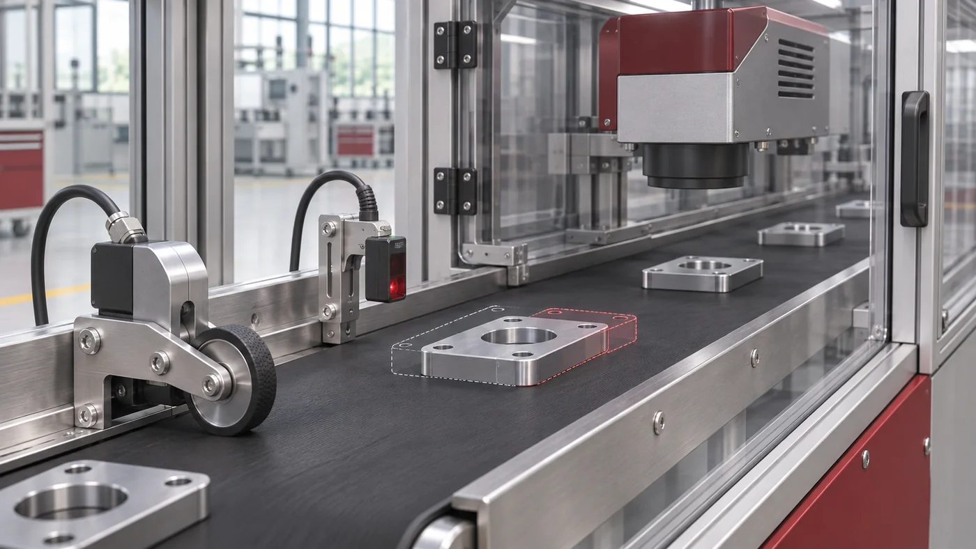
A mark is correctly positioned when the conveyor is stationary but shifts when it runs. Several causes can produce this behaviour. This guide covers troubleshooting on systems with encoder feedback and a product trigger. It separates distance measurement, timing delays and actual workpiece movement, so that a new position correction does not simply hide the error at one particular speed.
1. Check the encoder and distance scale independently
First record longitudinal and transverse offsets, rotation and marking dimensions relative to a fixed feature on the workpiece. A code that has shifted as a whole presents a different fault pattern from one stretched in the conveying direction. For camera measurements, also check calibration, perspective and workpiece orientation.
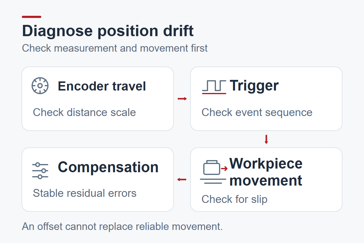
Then compare an independently measured conveyor travel distance with the change in counts recorded by the controller. Document whether the setting requires counts per millimetre or millimetres per count. Encoder resolution, signal-edge evaluation and the mechanical transmission ratio must be consistent. Repeat the comparison over different distances and speeds. A varying deviation cannot reliably be corrected with a single scale factor.
2. Break the trigger chain into individual events
Trace the signal path from the detected product edge, through the input and PLC, to acceptance of the marking job. Check the sensor edge, input filtering, possible multiple triggers and the controller ready state. A reflective or transparent product may produce a different switching point from the original sample.
At approximately constant speed, an additional delay corresponds approximately to a distance offset equal to speed multiplied by delay time. If the offset increases with speed, this points towards the timing chain but does not yet prove the cause. During acceleration, the actual distance travelled matters. Unsynchronised timestamps cannot simply be used to calculate short delays.
3. Compare workpiece movement with conveyor movement
An encoder that measures correctly initially confirms only the movement of the object it measures. Slip can occur between the drive roller and belt, measuring wheel and belt, or belt and product. Pay particular attention to start-up, braking, transfers and the release of accumulated products.
Under safe conditions, compare independent position measurements or suitable video recordings with encoder travel. Check contamination, belt tension, measuring-wheel contact and changes in weight or contact area. First investigate random slip mechanically; a fixed offset cannot compensate for it reliably. Avoid manual measurements on moving parts.
4. Assess guidance, orientation and focus separately
Transverse drift or a changing marking angle directs attention to guide clearance, workpiece rotation, clamping and mounting brackets. Measure position on the product, rather than only in the camera image. A format change may alter both product guidance and detection of the product edge.
Height changes and curved surfaces also affect focus and the apparent code outline. Distinguish an actual change in location from altered contrast or line appearance. Contaminated optics or a different material batch can reduce readability without the motion control being the cause.
5. Compensate only for reproducible residual errors
Adjust the settings supported by the particular controller only after distance measurement, triggering, conveying and guidance are stable. Change one variable at a time: distance scale, trigger distance, timing compensation or a fixed position offset. Record the unit, sign and recipe version; avoid applying the same correction in both the PLC and laser controller.
Power or pulse frequency settings do not replace a synchronisation check. Also verify whether the actual marking content can be completed within the available motion window. Functions, electrical interfaces and permitted input signals are device-specific. Work on these systems belongs in qualified hands and must be carried out with effective protective measures in place.
Close the change with a traceable test record
- Document the product, material batch, recipe, software version and measurement reference.
- Record the target speed, actual movement, encoder count and trigger path.
- Associate position deviation, angle, marking size and reading result with each test item.
- Record the value before and after each change, with a way to roll back.
- Test low-speed operation, the planned operating point, relevant acceleration conditions and format changes.
Tolerances and test scope follow from the drawing, marking area and downstream processing. After replacing a measuring wheel or moving a sensor, recheck the affected references. A readable code alone does not confirm an acceptable position.
For technical background, TRUMPF describes the interaction between sensor, encoder and motion compensation in marking on the fly. The SICK encoder-calibration documentation explains the distinction between pulses and counts using a specific system. Neither example replaces checking the controller actually installed.
Review your application with Lugsicher
Describe the material, code content, line cycle and the issue you have observed. This helps define the next checks for your application.
Discuss your project