
Planning Laser Fume Extraction: Capture, Filtration and Acceptance
Planning Laser Fume Extraction: Capture, Filtration and Acceptance
In laser marking, extraction forms part of workplace and process design. It should capture generated emissions as close to the source as possible while supporting stable operation. Cabinet size or nominal airflow alone is not enough to select a system. Material, process, capture point, filter arrangement and maintenance must work together.
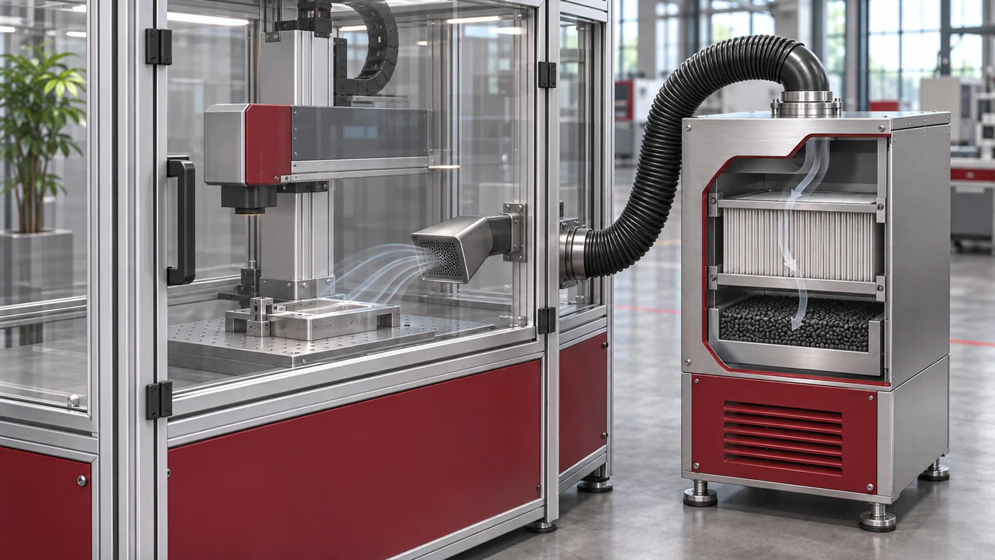
First describe the material and emission source
Before selecting a system, record all materials to be processed, including coatings, printing, adhesives and changing material variants. Add the laser process, power setting, processing duration, cycle rate and intended operating time. The same basic material name does not automatically describe the same emissions.
DGUV Information 213-729 on laser marking of plastics addresses inhalation hazards and protective measures within its defined scope. It makes clear that material composition and process conditions must be considered. A smell check or a visually clean environment therefore does not replace a competent assessment of the substances generated.
Design capture as close to the emission source as possible
Plan the capture device and enclosure together with the marking area. What matters is whether contaminated air is actually captured. Distance, openings, airflow direction and surrounding air movement affect the result. A higher nominal airflow does not automatically solve a poor arrangement.
Also consider hose length, cross-section, bends and the required pressure reserve. The value stated for the unit is not necessarily the airflow available at the capture point. With lightweight films or small products, the airflow must not cause uncontrolled changes in product position. Assess the design under its eventual installation conditions, including closed covers and adjacent air currents.
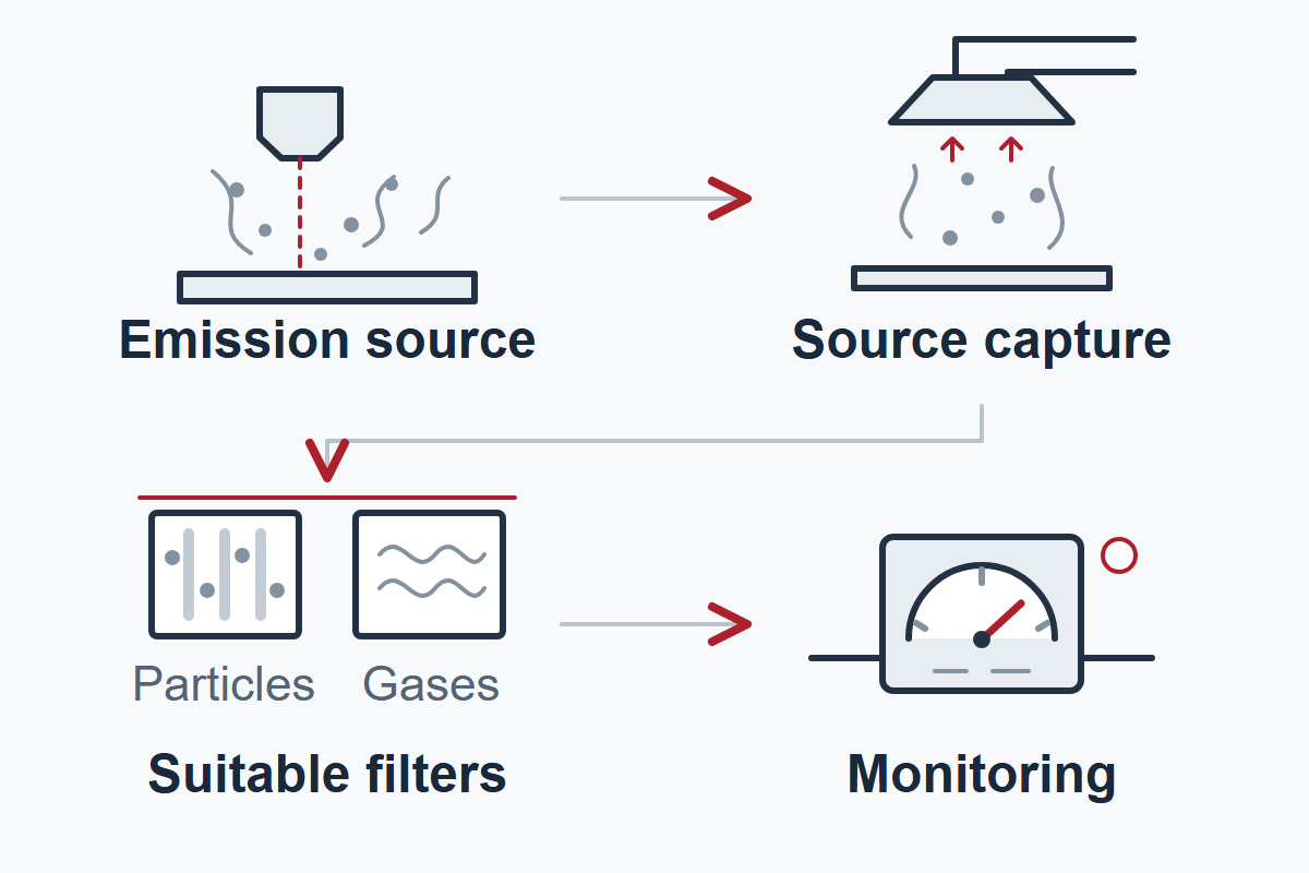
Assess particles and gaseous components separately
A particle filter stage and a stage for gaseous components perform different tasks. The appropriate combination depends on the substances actually generated and their loading. Ask for an explanation of the filter arrangement, intended substances, replacement criteria and configuration limits. A filter name alone does not describe a complete protective concept.
The choice between exhaust discharge and air recirculation also belongs in the workplace-specific assessment. Reduced odour does not demonstrate adequate removal of every relevant component. A product description therefore cannot provide general approval for recirculation. Make the decision with the responsible specialists and on the basis of the actual operating conditions.
Include monitoring and maintenance in line operation
Clarify which conditions are monitored and what each signal actually indicates: a running fan, filter loading, airflow and a unit fault are different pieces of information. Define the agreed response to a fault and test it during commissioning. A running indicator alone does not confirm effective capture at the source.
Plan accessible service points, suitable replacement filters and documented, low-dust cleaning in accordance with the manufacturers’ instructions and site procedures. Filter replacement follows the intended monitoring approach and the actual operating conditions. Reduced ink or ribbon consumption on a laser system does not eliminate filter and cleaning tasks.
Carry out acceptance checks on the complete installation
Testing must cover the installed arrangement, including capture devices, ducting, filters and intended materials. Use a shared checklist with the operator, integrator and extraction supplier.
| Assessment area | Clarify before approval |
|---|---|
| Material scope | Approved materials, coatings and changes |
| Capture point | Position, distance, airflow and accessibility |
| Filter arrangement | Particles and, where applicable, gaseous components, operating limits and replacement criteria |
| Air handling | Duct routing and the specified exhaust or recirculation arrangement |
| Fault response | Monitored conditions, indication, response and restart |
| Maintenance | Responsibility, safe execution, spare parts and documentation |
Keep a traceable record of the design, agreed tests and results. Additional materials or changes to ducting, enclosure and cycle rate can require reassessment. Only with this information can a suitable configuration be selected; the model designation alone is not a sufficient basis.
Review your application with Lugsicher
Describe the material, code content, line cycle and the issue you have observed. This helps define the next checks for your application.
Discuss your project