
Readable code, rejected product: diagnosing false rejects
Readable code, rejected product: diagnosing false rejects
A rejected product can be read with a handheld scanner. That does not yet prove a false reject: lighting, stationary conditions and reading angle differ from production conditions. What matters is which result was available for which product, whether it arrived in time, and which rule triggered rejection. The following sequence helps distinguish these events.
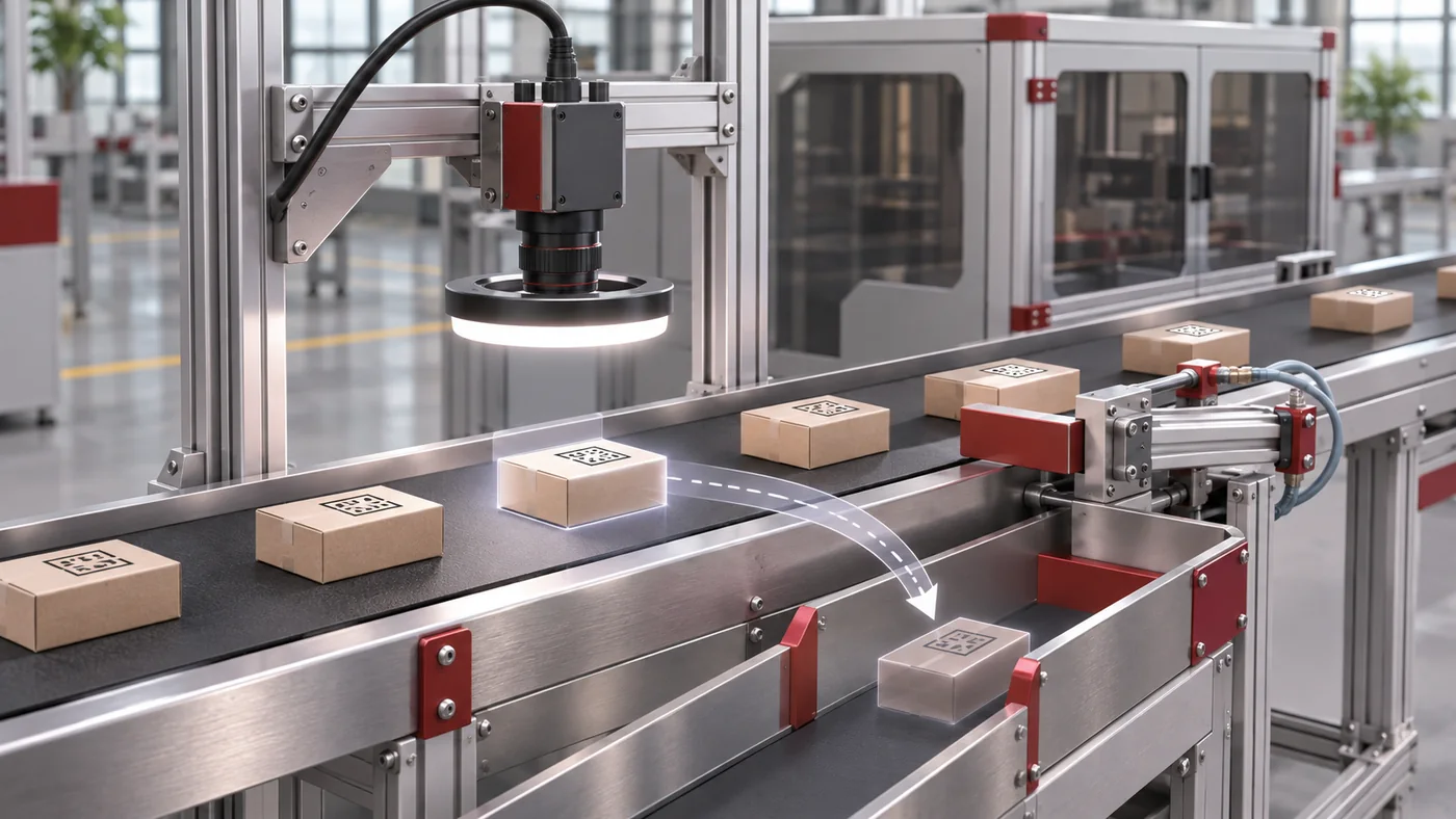
1. Preserve the original inspection image
Start with the image from the exact inspection cycle in question. Check the complete field of view, motion blur, overexposure, reflections and the quiet zone around the code. A later image of a similar product is not a substitute. Associate the original image and comparison sample using a product or trigger identifier.
On metal, machining marks and lighting direction can change contrast; films may have wrinkles or reflective areas. For labels, position within the inspection area also matters. Check exposure, viewing angle and focus together on the actual material. Contamination on the lens or protective window can also reduce the available imaging margin.
2. Assign a valid result to the correct cycle
The chain runs from product detection to image acquisition, evaluation, result transmission and acceptance by the PLC. An operator interface may still display the last successful read while the PLC has already detected a timeout in the current cycle.
Compare the trigger identifier, acquisition event, result-valid indication and receipt acknowledgement. Check how new results are signalled, accepted and reset. A continuously set good-result bit without a clear cycle association can conceal stale values. The shortest planned product spacing is the critical condition, rather than average output alone. Use synchronised time references or identifiable event numbers when comparing events across devices.
3. Test the link between inspection and rejection
Conveyor travel and further events separate the camera from the reject mechanism. A correct inspection result may therefore still be acted on at the neighbouring product. Investigate whether exactly one valid trigger creates one product record, and how missing, duplicate or manually removed products are handled.
A fixed time offset may no longer be suitable when conveyor speed changes. Distance-based tracking is also reliable only while the relationship between encoder travel and product movement remains valid. Test with separately controlled good and fault samples in varying sequences. Record which objects are actually rejected. These test items must not enter the normal product flow.

4. Evaluate the specific reason for rejection
Decoding and releasing a product are different decisions. A readable code may contain data for the wrong job or a serial number that has already been used. Distinguish at least the following findings:
| Finding | Relationship to check |
|---|---|
| Not read | Original image, position and acquisition conditions |
| Incorrect content | Job, data version and comparison specification |
| Duplicate code | Serial-number status and approved rework route |
| Late result | Cycle association, transmission and timeout |
| Quality criterion not met | Agreed inspection method and limit samples |
A device-internal reading score is not automatically a standardised quality grade. Lower thresholds only after evaluation using representative samples, also considering the risk of missed defects.
5. Distinguish the command, actuator movement and removed product
A PLC output initially confirms only the reject command. It proves neither complete actuator movement nor removal of the intended product. Check the compressed-air supply, return movement, spacing and possible displacement of an adjacent product, as appropriate for the machine arrangement.
A confirmation sensor also needs a defined product association and a suitable time or distance window. Otherwise, the next product may confirm the preceding operation. Rules for missing feedback, a failed reject operation or a full collection bin must match the line’s quality risk. Merely acknowledging the alarm does not replace this decision.
Compare a complete event record rather than isolated settings
For a suspect operation, link the product identifier, original image, decoded content, evaluation reason, result event, reject command and confirmation. Then test one hypothesis at a time. If exposure, threshold and delay are changed together, it is difficult to attribute an improved result to one cause.
The cross-check should cover relevant material batches, minimum product spacing, start-up and the planned production speed. This is a general diagnostic guide: the signals and logs actually available depend on the camera, controller and interfaces used in the project.
For further reading, Cognex distinguishes code reading from barcode verification. The DataMan protocols manual also uses a device-specific example to show how result validity, buffering and receipt acknowledgement interact. Its signal sequences are not a universal PLC specification.
Review your application with Lugsicher
Describe the material, code content, line cycle and the issue you have observed. This helps define the next checks for your application.
Discuss your project